Electronics & IT
Microcontrollers & ProgrammingGreen led cube
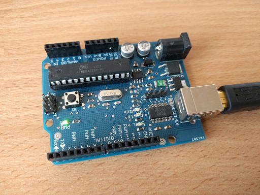
This project was under my mentor control, because it was my first electronic project. At the beginning teacher suggested to use Arduino to blink 8 LEDs in other ways (like running diode left, right, all on,all off, on,off,on,off etc.) It was good idea, becuase after that I knew that it's isn't as hard as I thought. Software on arduino needs to be written in C so I hadn't many problems with new enviroment, just some new functions like : digitalWrite(), digitalRead(), analogRead(), analogWrite().

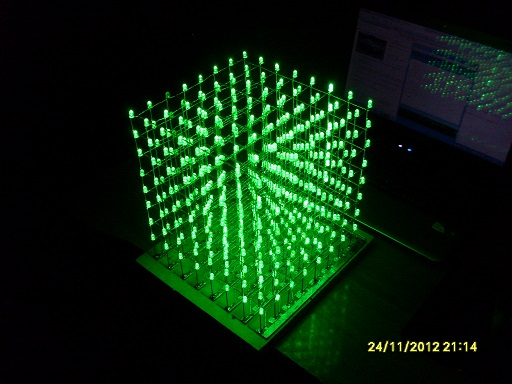
Now something about my cube. I have decided it will be green and here is parts list:
- Arduino Duemalinove (after just ATmega328 with external programmer)
- 700 Green LEDs (I thought it's enough but after I had to buy next 100 LEDs)
- 8x 74HC595 (shift register)
- 1x 74HC138 (3 to 8 decoder)
- 8x NDS8434 (FET-P transistors)
- 64x BC807-25 (PNP transistors)
- 1x 74HC245 (buffer for signals to registers)
- some resitors (to set LED's brightness)
- some capacitors (on power supply to microchips)
- connection wires
- DC power supply 5V (output current up to 2A)
Main part is of course arduino. It was good to start with it but after a time I realised that better is using simple processor permanently connected to the cube. Arduino is better for prototypes and testing. So after a long time looking for a good guide "How to burn arduino bootloader on ATmega328" I finally found it and it works! Now I can get something like arduino programmable by external programmer (I use USBasp, the cheapest) but much cheeper! For arduino I pay 80zl (polish currency) and for ATmega328, cristal 16MHz, small universal PCB,2 small capacitors, 5V stabilistor (7805) I pay no more than 10zl so only 12,5% of arduino's price with the same utility. In this category you can find small guide how to burn arduino bootloader to ATmega8 and ATmega328.
I found the cheapest diodes and bought 700 of them. When I was soldering 8x8 flat pieces, I think the 5%-10% of diodes were dead already and other 20% I have burned cause of soldering too long. So I had to buy more supplies.
74HC595 8-bit Shift registers are connected to each line with 8 diodes (in line). DATA OUT from register is connected to DATA IN in next register so I have something like 64-bit shift register. These microchips are easy to control. Just power and 3 controlling signals (LATCH, CLOCK, DATA). I wouldn't write here how it works, you can find it everywhere.
NDS8434 transistors are connected to output from 3 to 8 decoder to (it gives out 0 and in this project to turn on each level we need 1). Small PNP transistors are just to amplify the signal from shift register.
74HC138 (3 to 8 decoder) is used to turn on each level of my cube, for example 0,0,1 turns on 1 level etc.
Teacher suggested to use buffer 74HC245 to amplify the signal from ATmega to these 8 shift registers (all 8 must have CLOCK, LATCH connected to themselves)
Of course my teacher don't like me and my first electronic project I was building in SMD (Surface Mounted Devices) technology and his cube was in half SMD half Through-hole technology, becuase he was mounting on surface Through-hole parts. In my opinion it's a real good idea but you must draw electric paths by hand. After a long long time looking for a short circuits I finally completed my cube! Now, after some experience with Through-hole technology I prefer SMD too.

At the end I want to sum up my project. I have learned basics about microcontrollers and electronic, I have learned that something always will go wrong way (I have burned 5 or 6 shift registers), I was repairing it 20 times because always was something wrong, most problems I had with these registers but finally I have done it working. If you are planning an microcontroller circuit better but every parts with reserve, unless you are a good electronic :). Below is example video and you check do does my cube work.
Now the best part of this project is waiting for me - software. Cube is still waiting for me :)